- Visibility 135 Views
- Downloads 6 Downloads
- DOI 10.18231/j.ijmi.2020.017
-
CrossMark
- Citation
Ideal radiographs: An insight
- Author Details:
-
Latika Bachani *
-
Monika Singh
-
Anshul
-
Ashok Lingappa
Introduction
In British English the word “ideal” means: “Perfect, or “best possible”.[1]
John Cameron in 1970 stated that, “There was negligible risk from x-rays but many radiographs had poor image quality so that the risk from a false negative was significant”. Image quality and patient exposure are 2 important aspects of radiography. Inferior quality of the radiographs may affect the outcome of diagnosis and thereby jeopardize treatment.
In Sir H.M.WORTH’s words: “an ideal radiograph is the one which has desired density and overall blackness and which shows the part completely without distortion with maximum details and has the right amount of contrast to make the details fully apparent”.x`
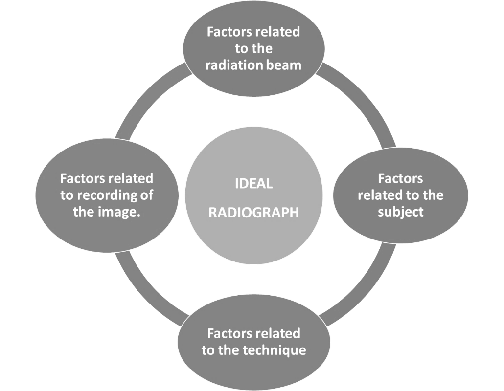
Factors related to radiation beam
Kilovoltage peak
Exposure time
Milliamperage
Tube-film distance
Focal spot
Collimation
Filtration
Equipment efficiency[2]
Focal spot
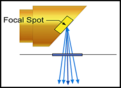
The focal spot is the area on the target to which the focusing cup directs the electrons from the filament ([Figure 2]). The sharpness of the radiographic image increases as the size of the focal spot-the radiation source decreases. Typically, the target is inclined about 20 degrees to the central ray of the x-ray beam. This causes the effective focal spot to be almost 1.x 1mm, as opposed to the actual focal spot, which is about 1 x 3mm.
Variation of focal spot size with changes in tube operating conditions
It is called as focal spot blooming
Focal spot size increases in direct proportion to tube current.
Focal spot size will decrease slightly with increasing kVp.[3]
Tube voltage (kVp)
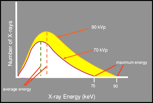
Voltage is the measurement of electrical force that causes electrons to move from the cathode to the anode.
Voltage increased: speed of electrons increased: force and energy of electrons increased: greater penetrating ability of the x-ray beam.
It is a measure of Beam energy([Figure 3]).
Dental radiography requires the use of 65-100 kVp.[4]
Tube current (mA)
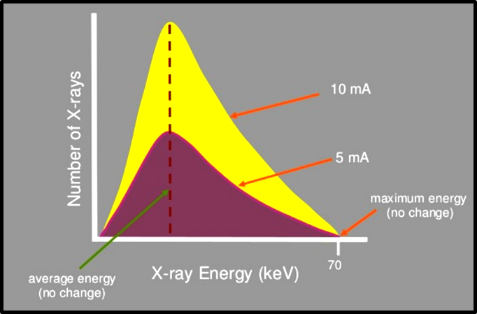
It is the flow of electrons through the tube, form cathode to anode and then back to the filament ([Figure 4]).
It determines the quantity of radiation or the number of photons reaching the patient and the film.
Exposure time (S)
Determines the duration of exposure hence the number of photons generated ([Figure 5]).
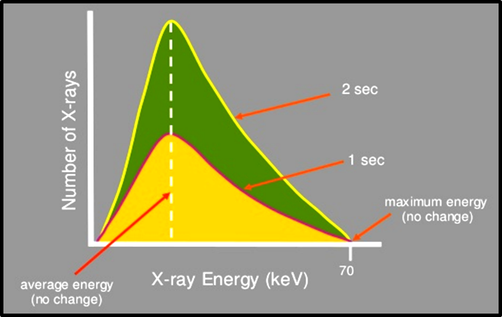
Beam Quantity = Tube current (mA) x Exposure time (s).
Filtration
An x-ray beam consists of spectrum of photons of different energies, but only photons of sufficient energy to penetrate through anatomic structures and reach the image receptor are useful for diagnostic radiology.
The rest of low energy photons are removed by placing an aluminium filter in the path of the x-ray beam. This process is called as filtration. [5]
It is of 2 types:
Inherent filtration: approx. 0.5-1mm
Added filtration: it is added in 0.5mm increments.
Total filtration: inherent plus added filtration. In dental radiography, machines operating at or below 70kVp, total filtration is minimum 1.5mm aluminium thickness. Above 70 kVp, it is 2.5mm.[3]
Beam intensity
It is the product of the quantity and quality per unit of area per unit of time of exposure.

Distance
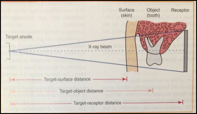
Distances that must be considered when exposing a dental radiograph are:
Target-surface distance
Target-object distance
Target-receptor distance
Distance has a marked effect on the intensity of the x-ray beam ([Figure 7]).[4]
Inverse Square Law
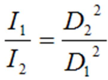
The inverse square law describes the principle of dose reduction as distance from the source increases.[5]
This assumes a point source. If radiation spreads over a spherical area, as the radius increases, the area over which the dose is distributed increases according to A=4πr2 where A is the area, π is pi and r is the radius of the sphere.
Therefore, the dose is proportional to the inverse of the square of the radius. Thus if you double the distance you reduce the dose by a factor of four.[3]
X-Ray Beam Characteristics
The ideal X-ray beam used for imaging should be:
Sufficiently penetrating, to pass through the patient and react with the film emulsion and produce good contrast between the different shadows.
Parallel, i.e. non-diverging, to prevent magnification of the image.
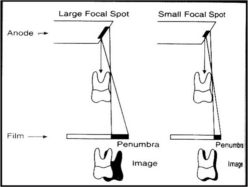
Produced from a point source, to reduce blurring of the edges of the image, a phenomenon known as the penumbra effect.[6]
Factors Related to the Subject
Subject thickness
Subject density
Subject density and thickness
Greater the subject thickness and density, greater the attenuation of X-ray beam, lighter the image obtained.
Order of densities:
Enamel>dentin>cementum>bone>muscle>fat>air
Denser objects: Radiopaque
Less dense objects: Radiolucent
Factors Related to Technique
Patient positioning
Placement and positioning of the film
Angulation of the X-ray beam[2]
Ideal patient positioning

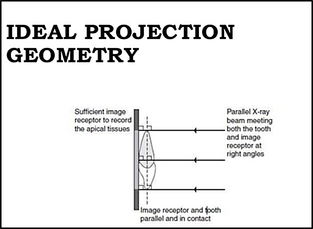
Basic Principles of Projection Geometry by: Manson and Lincoln
Focal spot should be as small as possible.
Focal spot to object distance should be as long as possible.
Object to film distance should be as small as possible.
Long axis of object and film plane should be parallel to each other.
X-ray beam should strike the object and film at right angles.
There should be no movement of the patient, tube or film during the exposure.
Anatomy of oral cavity does not always allow all these ideal positioning requirements to be satisfied.
So to overcome these problems, 2 techniques have been developed in periapical radiography:
Bisecting Angle Technique
Paralleling Technique[5]
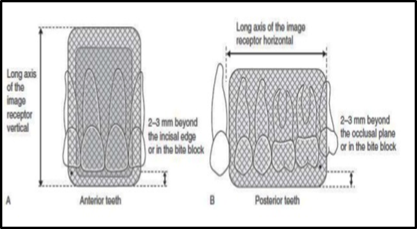
Ideal image receptor positioning
Receptor should be positioned to cover the prescribed area of the teeth to be examined.
Receptor must be positioned parallel to the crowns of both maxillary and mandibular teeth.
Angulation of the x-ray beam
Vertical angulation should be given as per the required tooth to be imaged.
Horizontal angulation should be kept zero to avoid overlapping of the proximal surfaces.
Vertical angulation is steep: foreshortening of the image
Vertical angulation is less: image elongation[4]
Factors related to recording of the image
Reduction in secondary radiation
Films and film storage
Intensifying screens
Film processing
Ways to reduce scattered radiation:
Use a relatively low kVp
Collimate the beam
Use grids in extraoral radiography.[4]
Film Storage
Ideally films should be stored at:
Cool, dry conditions.
Away from all sources of ionizing radiation.
Away from chemical fumes including mercury and mercury-containing compounds.[2]
Ideal dark room conditions
General cleanliness daily of work surfaces and film hangers.
Light-tightness checked yearly by standing in the dark room in total darkness with the door closed and safelights switched off and visually inspecting for light leakage.
Recommended room temperature : 700 F
> 900 F: film fogging.
Recommended relative humidity level : 50-70%
Safe-lighting
Low intensity light composed of long wavelengths in the red-orange portion of the visible spectrum.
Low wattage bulb 7.5 or 15 watts.
Safelight filter: to remove short wavelengths in the blue-green portion of the visible light spectrum that are responsible for damaging the x-ray film.
Should be placed atleast 4 feet away from the work area.
Films unwrapped too close to the safelight or exposed to the safelight for more than 2-3 min appear fogged.
Film processing solutions
Always made up to the manufacturer’s instructions.
Always at the correct temp.
Changed regularly, ideally every 2 weeks..
Monitored for deterioration: by using radiographs of step-wedge phantom.
Cassettes
Clean regularly.
Check for light-tightness
Check for screen-film contact
Characteristics of an Ideal Radiograph
Visual characteristics:
Density
Contrast
Geometric characteristics:
Sharpness or detail, resolution or definition
Magnification
Distortion
Anatomical accuracy of radiographic image
Adequate coverage of the anatomical region of interest.
Radiographic Density
The overall degree of darkening of an exposed radiographic film.[4]
Factors affecting the radiographic density:
First degree factors
Milliampere current (mA)
Kilo voltage peak (kVp)
Exposure time (s)
Source-to-film distance (d)
Increase in kVp increases the density.
Increase in mA increases the density.
Source-to-film distance (d): Reducing the distance between the focal spot and film also increases film density.
Second degree factors
Subject thickness: The thicker the subject, the more the beam is attenuated and the lighter the resultant image.
Subject density: The greater the density of astructure within the subject, the greater the attenuation of the x-ray beam directed through that subject or area.
Type of film
Screens
Grids
Amount of filtration used
Development conditions
Fog[2]
Radiographic Contrast
Defined as the differences in densities between light and dark regions on a radiograph.
A film that shows very light and very dark areas has high contrast or a short gray scale as there are few shades of gray from one extreme to the other.
A radiograph that has many shades of gray is referred to as one with low contrast or long gray scale. [Wide latitude]
Factors affecting radiographic contrast
Subject contrast
Film contrast
Operating kVp
Exposure time
Scattered radiation
Radiographic Speed
It is the amount of radiation required to produce a radiograph of standard density.
Film speed is expressed as the reciprocal of the exposure.
Controlled by silver halide grains and their silver content.
Kodak ultraspeed (group D)
Kodak Insight (group E and F)
Film processing at higher temp. Increases the film speed but increases film fog and graininess.[5]
Radiographic Latitude
It is the measure of the range of exposures that may be recorded as a series of usefully distinguishable densities on a film.
The wider the latitude of a film, the greater the range of object densities visualized.[7]
Radiographic Noise
It is the appearance of uneven density of a uniformly exposed radiographic film.
Major causes:
Radiographic mottle and radiographic artifact
Radiographic mottle is uneven density resulting from the physical structure of the film or intensifying screens.
Radiographic artifacts are defects caused by errors in film handling, such as fingerprints or bends in the film, or errors in film processing, such as splashing developer or fixer on a film or marks or scratches from rough handling.
On intraoral dental film, mottle may be seen as film graininess, due to visibility of silver grains in the film emulsion.
It is most evident when high-temperature processing is used.
Mottle is also evident when the film is used with fast intensifying screens.
Two important causes of the phenomenon are quantum mottle and screen structure mottle.
Quantum mottle is caused by a fluctuation in the number of photons per unit of the beam cross-sectional area absorbed by the intensifying screen.
Screen structure mottle is graininess caused by screen phosphors.
It is most evident when fast screens with large crystals are used.[6]
In diagnostic radiology, only quantum mottle has importance. Quantum mottle is most evident when fast film-screen combinations are used. It will be greater with high kVp x-rays because they produce a higher screen intensification factor.[8]
Geometric Characterstics
Image sharpness and resolution
Sharpness refers to the ability of a radiograph to reproduce distinct outlines of the object.
Resolution refers to the ability of the radiograph to reproduce smallest details of objects that are close together on a dental radiograph.
Panoramic film-screen combinations resolution: 5 line pairs per mm.
Periapical film resolution: more than 20 line pairs per mm.
Factors controlling sharpness of the image
Geometric unsharpness
Motion unsharpness
Film unsharpness
Fog unsharpness
Intensifying screen unsharpness
Geometric unsharpness
Focal spot size
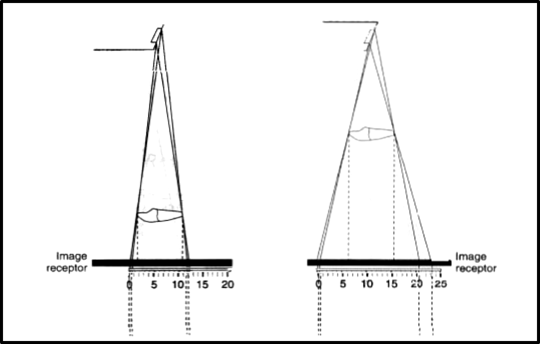
Target-film-distance
Object-film-distance

Motion unsharpness
Due to movement of:
Patient
Tube head
Film
It can be reduced by decreasing the exposure time.
Film unsharpness
Grain size of emulsion crystals
Single and double emulsion and film thickness:
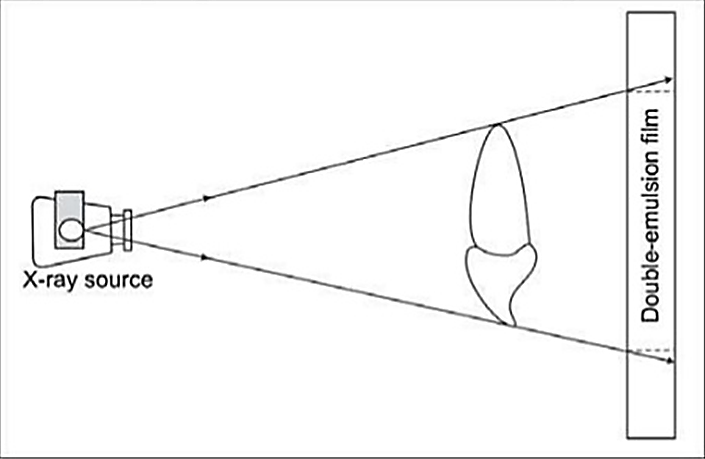
The presence of an image on each side of a double emulsion film also causes a loss of image sharpness through parallax. Parallax results from the apparent change in position or size of a subject when it is viewed from different perspectives. Because dental film has a double coating of emulsion and the x-ray beam is divergent, the images recorded on each emulsion vary slightly in size. In intraoral images, the effect of parallax on image sharpness is unimportant but is most apparent when wet films are viewed. Under these conditions the emulsion is swollen with water and the loss of image sharpness caused by parallax is more evident. When intensifying screens are used, parallax distortion contributes to image unsharpness because light from one screen may cross the film base and reach the emulsion on the opposite side. This problem canbe solved by incorporating dyes into the base that absorb the light emitted by the screens.
Fog unsharpness
Scattered radiation
Unsafe safety light in the darkroom
Chemical fog: due to prolonged development or development at high temperature.
Potassium bromide or restrainer prevents chemical fogging.
Radiograph should be adequately rinsed before putting it in the fixer.
After fixing it should be thoroughly washed.
Temp. Difference between processing solution and rinsing water should not be more than 150 F.
Film should be adequately dried.[4]
Intensifying screen unsharpness
Improper film contact with the screen.
Radiographic mottle: it refers to uneven density resulting from the physical structure of the film or the intensifying screen.[8]
Image Magnification
It refers to a radiographic image that appears larger than the actual size of the object it represents.
It is because of the divergent path of the x-rays from the focal spot.
Factors affecting image magnification
Target - film distance
Object - film distance
Use of intensifying screens

Intensifying screens
Screens increase the distance between the film and the object and hence contribute to a certain amount of image magnification.[2]
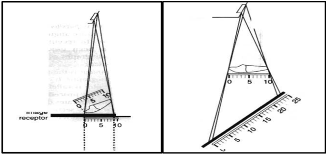
Image Distortion
It refers to the variation in the true size and shape of the object being recorded.
It may occur due to unequal magnification of different parts of the same object.
It may be due to:
Object-film alignment
X-ray beam angulation
Anatomical Accuracy
It occurs when the anatomical structures are reproduced on the film in the same relationship as they normally appear.
A radiograph is said to have anatomical accuracy when:
Labial and lingual CEJ of the anterior teeth are superimposed.
Buccal and lingual cusps of posterior teeth are superimposed.
Buccal and lingual portions of the alveolar crest are superimposed.
Radiographic Coverage
Adequate coverage of the area of interest depends upon:
Proper alignment of the film and radiation beam to the area of interest.
Proper selection of the film type.
Proper selection of the projection technique.[7]
Ideal Quality Criteria
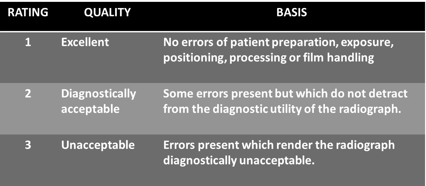
IOPA
The image should include the correct anatomical area together with the apices of the tooth/ teeth under investigation with at least 2mm of periapical bone.
There should be no overlap of proximal surfaces of the teeth.
The image should have acceptable definition with no distortion or blurring.
The image should have optimum density and contrast to facilitate interpretation.
The film should be free of cone cutting and other film handling errors.
The desired density and contrast for the film captured images will depend on the clinical reasons for taking the radiograph, eg.,
OPG
All the upper and lower teeth and their supporting alveolar bone should be clearly demonstrated.
The whole of the mandible should be included.
Magnification in the vertical and horizontal planes should be equal.
The right and left molar teeth should be equal in their mesio-distal dimension.
The density across the image should be uniform with no air shadow above the tongue creating a radiolucent band over the roots of the upper teeth.
The image of the hard palate should appear above the apices of the upper teeth.
Only the slightest ghost shadows of the contralateral angle of the mandible and the cervical spine should be evident.
There should be no artefactual shadows due to dentures, earrings and other jewelry.
The patient identification label should not obscure any of the above features.
The image should be clearly labelled with the patient’s name and date of the examination.
The image should be clearly marked with a Right and/or Left letter.[9]
Conclusion
An ideal radiograph is the end result of the interplay of various factors as described above. It should be capable of providing all the necessary information required to achieve a correct diagnosis. Furthermore, a good radiograph not only helps in making a proper diagnosis, but it also aids in adequate treatment planning. Hence a radiologist must be aware of the various characteristics of an ideal radiograph and the various factors governing them to achieve a proper diagnosis.
Source of Funding
None.
Conflict of Interest
None.
References
- . . . [Google Scholar]
- F R Karjodkar. . Textbook of Dental and Maxillofacial Radiology 2011. [Google Scholar]
- T S Curry, J E Dowdey, R C Murry. . Christensen’s physics of diagnostic radiology 1990. [Google Scholar]
- J M Iannucci, L J Howerton. . Dental radiography principles and techniques 2011. [Google Scholar]
- S C White, M J Pharoah. . Oral radiology: principles and interpretation 2008. [Google Scholar]
- E Whaites. . Essentials of dental radiography and radiology 2002. [Google Scholar]
- H H Frommer. Radiology In Dental Practice. . [Google Scholar]
- G T Barnes. Radiographic mottle: A comprehensive theory. Med Physics 1982. [Google Scholar]
- Introduction
- Factors related to radiation beam
- Focal spot
- Variation of focal spot size with changes in tube operating conditions
- Tube voltage (kVp)
- Tube current (mA)
- Exposure time (S)
- Filtration
- Beam intensity
- Distance
- X-Ray Beam Characteristics
- Factors Related to the Subject
- Factors Related to Technique
- Film Storage
- Characteristics of an Ideal Radiograph
- Radiographic Density
- Radiographic Contrast
- Radiographic Speed
- Radiographic Latitude
- Radiographic Noise
- Geometric Characterstics
- Image sharpness and resolution
- Factors controlling sharpness of the image
- Geometric unsharpness
- Motion unsharpness
- Film unsharpness
- Fog unsharpness
- Intensifying screen unsharpness
- Image Magnification
- Image Distortion
- Anatomical Accuracy
- Radiographic Coverage
- Ideal Quality Criteria
- IOPA
- OPG
- Conclusion
- Source of Funding
- Conflict of Interest
