- Visibility 30 Views
- Downloads 4 Downloads
- DOI 10.18231/j.ijmi.2021.010
-
CrossMark
- Citation
Evaluation of zygomatic bone region for placement of quad zygomatic implants using CBCT in postmenopausal women
Introduction
The zygomatic bone (ZB) has been an effective option in the rehabilitation of the atrophic edentulous maxilla. Postmenopausal women are more susceptible to primary osteoporosis since osteoporosis is closely related to estrogen deficiency. Drop of estrogen levels in menopausal time leads to more bone resorption than formation. The placement of a zygomatic implant is a favourable approach for patients with atrophic maxillae[1], [2], [3] with a long-term survival rate of 94.2% to 100%.[4], [5], [6], [7]
In the maxillary edentulous patients with severely atrophic maxillae, more than one zygomatic implant is required to place in each zygoma to support the prosthesis, and currently, the placement of quad zygomatic implants is suggested where the placement of zygomatic implants requires accurate evaluation on the characteristics of zygoma so that two zygomatic implants can be placed in the proper regions of the same zygoma. These regions provide the largest bone-implant contacts (BICs) for the stability concern and keep away from the adjacent critical structures like infratemporal fossa (ITF) to avoid the intrusion complications especially in postmenopausal women who had low bone mass.
Previously, some studies measured the thickness of zygoma, in the region near the inferioanterior position to the jugale, which has the largest thickness, which could be the optimal choice to place the apex of a zygomatic implant.[8], [9] But these studies were with less precision of linear measurement because the thickness was obtained by measuring on cadavers. Hence the main aim of this study was to evaluate the ZB using cone-beam computed tomography (CBCT) images to determine, characteristics similar to pneumatizations (CSPZB), evaluated the thickness in different regions of the zygoma, assessed the BICs of the apexes of zygomatic implants, which were virtually placed in different regions on a computer using planning software, and assessed the incidence of intrusion into the ITF.[10]
Materials and Methods
Patients
This study was conducted at G Pullareddy Dental College, Kurnool, Andhra Pradesh, India from 2018 to 2021. The study got approved by the college Ethical Committee of G Pullareddy Dental Hospital. All patients had to sign a written consent form. A total of 120 female patients were included who has taken CBCT images for implant placement of age group between 45 years to 65years. The exclusion criteria were patients with anatomic abnormalities in zygoma or maxilla, patients with any facial asymmetry. For dentate patients, patients who lost one or more maxillary premolars or molars on both sides.
CBCT standardization
A CBCT scanner with a flat panel detector was used in all cases (i-Cat; Imaging Sciences International, LLC, Hatfield, Pennsylvania). The voxel size was 0.2 mm 3 0.2 mm 3 0.2 mm. The exposure volume was set at 0.4 mm. Manufacturer recommended settings were employed. The Frankfort plane was used and the scan range was from the supraorbital edge to mandible. DICOM files of images were imported and analyzed using the planning software Nobel Clinician (Nobel Biocare AB, Goteborg, Sweden).
Analysis of image
Investigation of measurements done under the supervision of two experts in oral and maxillofacial surgery and radiology. The examiners looked for images with characteristics similar to those described by Tyndall and Matteson for pneumatization of articular eminence: a radiolucent (hypodense) defect with an appearance similar to mastoid air cells, with no enlargement and cortical destruction. The type was also classified as unilocular or multilocular. The Unilocular aspect was identified as a single hypodense oval defect with well-defined bony borders, whereas the multilocular aspect was identified as numerous hypodense small cavities.[11]
For assessment of thickness and bone-implant, contact reference points were taken from the frontal view, a line passed through the bilateral lowermost points on the infraorbital margin was designated as line IM ([Figure 1]). A line that passed through the most lateral point on the orbital margin parallel to the middle line plane was designated as line LM ([Figure 1]). The intersection point of line IM and line LM was designated as Point C ([Figure 1]). The intersection point of the angular bisector of line IM and line LM and the orbital margin was designated as Point O (Figure 1A). Line 1 (L1) connects Point O to Point C ([Figure 2]). Line 2 (L2) and Line 3 (L3) were orderly parallel to L1 posteriorly at the distance of 5 mm (Figure 1C). The L1 to L3 were confined from the orbital margin to the inferior border of the zygoma, and the region from L1 to L3 was the apex of the zygomatic implants may be presented. The L1 and L3 were quartered with 6 points namely A1, B1, C1, A3, B3, and C3 from the tops to the bottoms ([Figure 3]). LA, LB and LC lines pass through A, B, and C points respectively ([Figure 3]). The LA, LB, and LC intersected with L1 and L2 with 6 points namely A1, A2, B1, B2, C1, and C2, respectively ([Figure 3]). Zygoma was divided into the superior, middle, and inferior parts by LA, LB, and LC and regions passed through by LA, LB, and LC were represented as the superior, middle, and inferior regions of the zygoma ([Figure 3]).
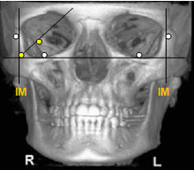
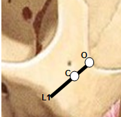
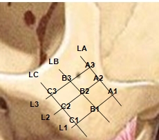
Measurements recorded
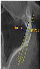
The zygomatic thicknesses at a total of 9 points in the superior, middle, and inferior regions and the zygomatic length at L1-L3 were, respectively, measured in all cases ([Figure 4]). Zygomatic BICs were measured by placing mesial and distal implants along L1(C1-A1) and at L3(C3-A3) lengths using virtual implants planning software. The coronal points of the mesial implant and distal implant were at Point C1 and C3, respectively. The apical points of the mesial implant were located on Point A1 and that of the distal implant was located on Point A3. The zygomatic BIC was the average value of zygomatic BIC length on the facial and the temporal sides ([Figure 5]).
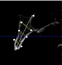
Statistical analysis
All analyses were performed with SPSS software. Differences in the zygomatic thickness and length between groups were compared using an independent student t-test. The zygomatic thickness and length were correlated using the Pearson correlation analysis and the Pearson correlation coefficient (R). A P value of <.05 was considered to be statistically different.
Results
Demographic data of study
This study recruited 120 eligibly consecutive patients (mean age of 49.8 years;) were maxillary dentate patients.
Laterality and type
Only 3.9 (3.3 %) individuals presented characteristics similar to pneumatization in the ZB (CSPZB); 36 (30.4 %) had unilateral modifications and 82 (69.6 %) had in both sides. If we consider all ZB, modifications were in 3.3(2.8 %) of the unilocular type shown in [Table 1].
The zygomatic thicknesses at points
The zygomatic thicknesses were measured on a total of 120 zygomata. The zygomatic thickness at each point shown in [Table 2]. The differences of the thicknesses at points on superior, middle, and inferior areas were significantly different The largest thickness on the superior, middle, and inferior areas were at Point A2, Point B2, and Point C1, with a mean value of 7.92+/-2.10 mm, 7.01+/-1.62 mm, and 6.62+/-1.64 mm, respectively.
On the superior area, the thickness gradually decreases from Point A2 to the anterior point of Point A1 and the posterior point of Point A3; on the middle area, the thickness gradually decreases from Point B2 to the anterior point of Point B1 and the posterior point of Point B3; on the inferior area, the thickness decrease from Point C1 to the posterior point of Point C3).
Length of zygomatic bone at lines
The length of each line was measured and are shown in [Table 3]. The differences of the lengths at lines were significantly different.
The zygomatic BICs of the virtual implants at points
The zygomatic BICs were obtained by measuring the virtually placed implants on 120 zygomata. On the superior area, Point A3 provided the largest zygomatic BIC, and gradually decreased from at Point A3 to A1; on the middle area, Point B2 provided the largest zygomatic BIC and decreased from at Point B2 to the posterior point of Point B3 and the anterior point of Point B1, respectively; on the inferior area, Point C1 provided the largest BIC and decreased from at Point C1 to the posterior point of Point C3 shown in [Table 4].
|
|
Sample |
CSPZB |
% |
|
Individuals |
120 |
3.9 |
3.3% |
|
Laterality |
|
|
|
|
Unilateral |
120 |
36 |
30.4% |
|
Bilateral |
120 |
82 |
69.6% |
|
TYPE |
|
|
|
|
Unilocular |
120 |
- |
- |
|
Multilocular |
120 |
3.3 |
2.8% |
|
Area |
Point |
Thickness |
P value |
|
Superior |
A1 |
6.21+/-2.23mm |
<.001 |
|
|
A2 |
8.01+/-2.10mm |
|
|
|
A3 |
7.04+/-1.68mm |
|
|
Middle |
B1 |
6.01+/-1.85mm |
<.001 |
|
|
B2 |
7.01+/-1.62mm |
|
|
|
B3 |
6.03+/-1.52mm |
|
|
Inferior |
C1 |
6.65+/-1.64mm |
<.001 |
|
|
C2 |
6.23+/-1.59mm |
|
|
|
C3 |
5.54+/-1.51mm |
|
|
Line |
Length (in mm) |
p Value |
|
L1 |
25.47+/-3.09mm |
<.001 |
|
L2 |
26.24+/-3.01mm |
|
|
L3 |
28.49+/-3.04mm |
|
Region |
Apical point |
BIC (mm) |
P values |
Implant into Zygoma (%) |
|
Superior |
A1 |
4.12+/-1.82mm |
<.001 |
9.7 |
|
|
A2 |
9.28+/-3.31mm |
|
19.8 |
|
|
A3 |
15.92+/-4.16mm |
|
26.9 |
|
Middle |
B1 |
6.35+/-3.12mm |
<0.001 |
16.5 |
|
|
B2 |
12.02+/-3.62mm |
|
27.9 |
|
|
B3 |
11.86+/-3.48mm |
|
29.7 |
|
Inferior |
C1 |
8.38+/-3.67mm |
<0.001 |
22.1 |
|
|
C2 |
11.41+/-3.38mm |
|
31.2 |
|
|
C3 |
10.21+/-3.05mm |
|
26.4 |
Discussion
The zygomatic bone (ZB) is a quadrangular structure that can be compared to a pyramid. The importance of zygomatic bone is increased in many clinical conditions especially in dental Implantology. In dental implants, when there is no adequate bone volume permitting their anchorage, zygomatic implants are advised as a partial or complete alternative to bone augmentation procedures.
The quality and quantity of jaw bone is affected by menopause. Osteoporosis is a systemic disease which is seen in postmenopausal women. It is characterised by decrease bone mass density especially in buccal bone region. In the present study even though bone mass is not measured but the more stable region to place implants was analysed.
Due to its increased clinical importance, it is important that evaluation of ZB has been performed in imaging techniques significantly in women who are in post menopausal period. Because, women in this stage are more prone with osteoporosis that further leads to severe bone resorption. The bones of the skull contain many air-filled cavities, referred to pneumatization. These areas can arise at different locations, and are preceded by a formation of bone cavities, a physiological process related to periosteal activity.[12]
For that reason, several studies had evaluated the prevalence of pneumatisation in areas of zygomatic process and presented as characteristics similar to pneumatizations (CSPZB) concerning the laterality and type using CBCT images. Cone beam computed tomography (CBCT) is the ideal image to evaluate this bone which is pyramidal and must be evaluated 3 dimensionally.
Results from the study showed only 3.3% of individuals presented characteristics similar to pneumatization in the ZB (CSPZB); 36 had unilateral modifications and 82 had in both sides. If we consider all ZB, modifications were in multilocular type 3.9, similar to the result by Ladeira et al.[13] The results of the thicknesses of zygoma were ranges from 5.54 to 8.01 mm, and the lengths were from 25.47 to 28.49 mm. When compared to the reports by Brazilian and Belgian of zygomatic measurement, the results from this study are larger.[14]
The largest BIC obtained on the superior, middle, and inferior areas of zygoma were at points A3 and B2 points with the largest thickness. Some other studies proposed that the bone thickness for placing the apex of the zygomatic implant was to be at least 5.75 mm,[15], [16] but this study found that Point A3, which provided the largest BICs with no intrusion complication, had a thickness of 7.04 mm.
Quad zygomatic implants approach
It needs 2 regions on a zygoma for placing zygomatic implants, one at the apex where the mesial implant should be placed and above that the distal implant is placed. For this purpose the superior area was designed for mesial implant placement and middle or inferior areas were designed to place the distal implant. Point A3 on superior area provided the largest BIC, and Point B2 on the middle or inferior areas. But the second zygomatic implant placement on inappropriate region increases at risk of intrusion of implant into the ITF.[17]
From the results of this study, it was seen that the apex of the distal implant placed at Point B3, Point C1, Point C2, and Point C3 occurred implant intrusion into the ITF. Hence, for obtaining the largest BICs while retaining the minimum incidence of intrusion into the ITF, Point A3 and Point B2 were the most promising points for quad zygomatic implants placement which indicates the postero-superior region and center of zygoma for the apex of the mesial implant and distal implants respectively. Therefore, to obtain the largest BICs, it is suggested to produce longer zygomatic implants.
Certain advantages of this study are large sample size, measurement of the thicknesses and lengths of 240 zygomata on 120 patients. The linear measurements based on CBCT images are accurate, reliable[18], [19], [20], [21], [22] and repeatable when compared to measuring on cadavers. One of the main limitations of this study is, the BICs were obtained by the virtually placed zygomatic implants on the computer using the planning software rather than by clinical practice. The bone density of zygoma was also not taken into account in this study.
Conclusion
Within limitations of the study, it can be concluded that for obtaining largest BICs while avoiding the intrusion complications, the suggested area is postero-superior region (Point A3) and the center of zygoma (Point B2) for the placement of quad zygomatic implants in post-menopausal women.
Source of Funding
None.
Conflict of Interest
The authors declare that there is no conflict of interest.
References
- SM Parel, P Brånemark, L Ohrnell, B Svensson. Remote implant anchorage for the rehabilitation of maxillary defects. J Prosthet Dent 2001. [Google Scholar] [Crossref]
- BL Schmidt, MA Pogrel, CW Young, A Sharma. Reconstruction of extensive maxillary defects using zygomaticus implants. J Oral Maxillofac Surg 2004. [Google Scholar] [Crossref]
- PO Davor. 5-year outcome of cross-arch prostheses supported by four immediately loaded zygomatic implants: a prospective case series. Eur J Oral Implantol 2015. [Google Scholar]
- M Esposito, HV Worthington. Interventions for replacing missing teeth: dental implants in zygomatic bone for the rehabilitation of the severely deficient edentulous maxilla. Cochrane Database Syst Rev 2013. [Google Scholar] [Crossref]
- MC Goiato, EP Pellizzer, A Moreno, H Gennari-Filho, DM dos Santos, JF Santiago. Implants in the zygomatic bone for maxillary prosthetic rehabilitation: a systematic review. Int J Oral Maxillofac Surg 2014. [Google Scholar] [Crossref]
- P Malo, M Nobre, A Lopes, A Ferro, S Moss. Five-year outcome of a retrospective cohort study on the rehabilitation of completely edentulous atrophic maxillae with immediately loaded zygomatic implants placed extra-maxillary. Eur J Oral Implantol 2014. [Google Scholar]
- W Feng, M Alberto, L Guohao, Y Wu, F Monje, HL Wang. Reliability of four zygomatic implant-supported prostheses for the rehabilitation of the atrophic maxilla: a systematic review. Int J Oral Maxillofac Implants 2015. [Google Scholar]
- MB Rigolizzo, JA Camilli, CE Francischone. Zygomatic bone: anatomic bases for osseointegrated implant anchorage. Int J Oral Maxillofac Implants 2005. [Google Scholar]
- N Takamaru, H Nagai, G Ohe, T Tamatani, K Sumida, S Kitamura. Measurement of the zygomatic bone and pilot hole technique for safer insertion of zygomaticus implants. Int J Oral Maxillofac Surg 2016. [Google Scholar] [Crossref]
- JI Cawood, RA Howell. A classification of the edentulous jaws. Int J Oral Maxillofac Surg 1988. [Google Scholar] [Crossref]
- DA Tyndall, SR Matteson. Radiographic appearance and population distribution of the pneumatized articular eminence of the temporal bone. J Oral Maxillofac Surg 1985. [Google Scholar] [Crossref]
- L Ojala. Pneumatization of the bone and environmental factors; experimental studies on chick humerus. Acta Otolaryngol Suppl 1957. [Google Scholar]
- DBS Ladeira, GLR Barbosa, MCC Nascimento, AD Cruz, DQ Freitas, SM Almeida. Prevalence and characteristics of pneumatization of the temporal bone evaluated by cone beam computed tomography. Int J Oral Maxillofac Surg 2013. [Google Scholar] [Crossref]
- MB Rigolizzo, JA Camilli, CE Francischone. Zygomatic bone: anatomic bases for osseointegrated implant anchorage. Int J Oral Maxillofac Implants 2005. [Google Scholar]
- RG Triplett, SR Schow, DM Laskin. Oral and maxillofacial surgery advances in implant dentistry. Int J Oral Maxillofac Implants 2000. [Google Scholar]
- JL Frodel, GF Funk, DT Capper. Osseointegrated implants: a comparative study of bone thickness in four vascularized bone flaps. Plast Reconstr Surg 1993. [Google Scholar]
- BR Chrcanovic, DR Oliveira, AL Custódio. Accuracy Evaluation of Computed Tomography–Derived Stereolithographic Surgical Guides in Zygomatic Implant Placement in Human Cadavers. J Oral Implantol 2010. [Google Scholar] [Crossref]
- P Pittayapat, MM Bornstein, TSN Imada, W Coucke, I Lambrichts, R Jacobs. Accuracy of linear measurements using three imaging modalities: two lateral cephalograms and one 3D model from CBCT data. Eur J Orthod 2015. [Google Scholar] [Crossref]
- S Veyre-Goulet, T Fortin, A Thierry. Accuracy of Linear Measurement Provided by Cone Beam Computed Tomography to Assess Bone Quantity in the Posterior Maxilla: A Human Cadaver Study. Clin Implant Dent Related Res 2008. [Google Scholar] [Crossref]
- CR Moreira, MAO Sales, PML Lopes, MGP Cavalcanti. Assessment of linear and angular measurements on three-dimensional cone-beam computed tomographic images. Oral Surg Oral Med Oral Pathol Oral Radiol Endod 2009. [Google Scholar] [Crossref]
- X Liang, RB Jacobs, L Li. A comparative evaluation of cone beam computed tomography (CBCT) and multi-slice CT (MSCT) part II: on 3D model accuracy. Eur J Radiol 2010. [Google Scholar]
- PW Poeschl, N Schmidt, G Guevara-Rojas, R Seemann, R Ewers, HT Zipko. Comparison of cone-beam and conventional multislice computed tomography for image-guided dental implant planning. Clin Oral Investig 2013. [Google Scholar] [Crossref]
